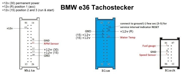
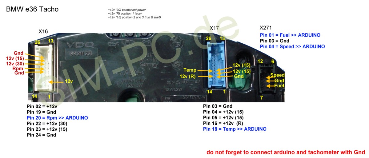
BMW e36 Tacho zu Arduino
Damit das Tacho auch ordnungsemäß funktioniert, muss es wie auf der Zeichnung angeschlossen werden:

BMW Tacho an Arduino – Video1
So, hier mal ein erstes Video von meinem Tacho am Arduino Nano
Platine für Drehzahl und Ganganzeige im BMW e36 Cockpit
Drehzahl und Ganganzeige
8 x 3mm LED mit eingebautem Vorwiderstand,
1 x 7 Segment, 9mm Common Cathode (FYS-3612),
8 x 150 ohm Widerstände


